Heres an alternate circuit that Crater made.
Interesting circuit...especially the tone control arrangement!
My take & it's worth what you paid for it, assuming this circuit is correct (bar the 220k resistor value) then yes it will always "suck":
a) The 220k resistor is always in the circuit and as per the reasons stated in the thread Frono has linked above, it acts as a voltage divider with the volume pot, so you are always losing some signal (i.e volume) from the raw pickup output as a result.
b) With the tone pot fully one way say such that there is no resistance between the middle lug (pickup output) to the two two caps (0.044 mfd), then there is a direct signal to ground through the caps, rolling off lots of highs (standard tone pot action)
c) With the tone pot fully the other way say such that there is no resistance between the middle lug (pickup output) to the single cap in series with the inductor & with the suck switch open, then there is a direct signal to ground through the cap in series with inductor. Going through the cap to ground will want to drop off highs. Going through the inductor to ground will want to drop off lows. I guess this would do both! I'm guessing this is the "suck" position.
d) With the tone pot as in "c)" above with the suck switch closed, then the cap is is now shunted across the 220k resistor. This would add more highs (& volume) direct from the pickup to the output. The inductor is still in circuit and would still siphon off some lows to ground depending on it's value. So in this case I would expect more volume, overall brighter signal & more mids (as it is a decent sized cap) than in the previous arrangement.
e) If the tone pot was turned fully the other way from d) above, with the switch closed, then it would probably sound quite similiar to the scenario "b)" above as the there would be 200k (pot resistance) between what is now the shunt cap, mitigating it's effect.
f) With the tone pot in between the two extreme positions you would get both effects happening but with each reduced from maximum, depending where the pot position is.
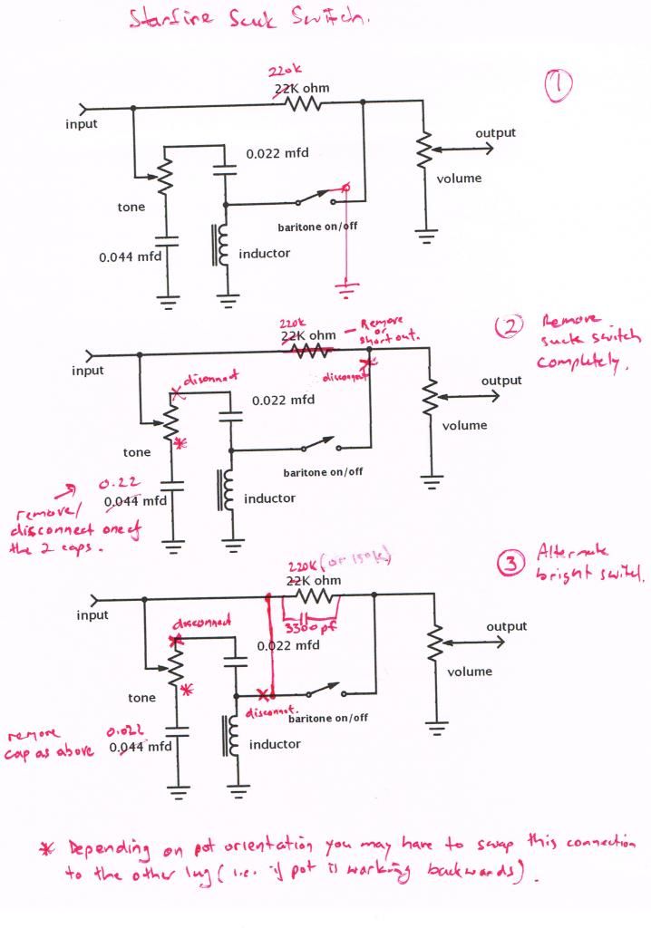
Saying all that, Wisconsindead's sketch implies to me that there is terminal to ground when the switch is up. I have drawn it on diagram 1 in my markups below. If this is the case then when the switch is up, the inductor is bypassed to ground & effectively removed from the circuit. The 0.022 mfd cap is now shorted to ground like a normal tone circuit. So at this extreme the pot would just roll off highs but not as much as if turned fully the other way as the capacitance to ground is smaller. When the switch is down (closed as before) then it would have the same behaviour as described in d) above - i.e. cap becomes a shunt across the 220k resistor & the inductor is back in play.
My sketches below & some suggestions below it.
Circuit 2 - Remove suck switch completely:-
a) disconnect 0.022 mfd cap (the one connected to the inductor) from the tone pot
b) disconnect switch from the volume pot/220 k resistor junction (or at the switch itself)
c) remove 220 k resistor from the circuit i.e. remove the resistor & wire the middle lug of the tone pot directly to the volume pot where the resistor currently is connected to. Alternatively you could leave the resistor in & just put a shunt across it i.e. wire in the cable between the tone & volume pots where the resistor is currently connected to.
d) Option - you could remove one of the two caps that are wired in parallel to reduce the overall capacitance & thus effect of the now much more normal tone control.
This should give you a normal tone control & more volume as the 220k resistor is now out of the circuit & the output receives almost the full signal of the pickup (you will still get some rolling off of the highs through the tone control even when the tone pot is on full, especially as it is only a 200k pot - with a higher value pot this will be diminished)
Circuit 3 - Use the switch as a bright switch of sorts:-
This is what was done on hagmeat's JSII in the thread Frono linked above. One switch position is normal (as per Circuit 2) the other position rolls off some lows but should still give you decent volume.
a) disconnect 0.022 mfd cap (the one connected to the inductor) from the tone pot
b) disconnect the inductor from the switch
c) place a 3300pf cap across the 220k resistor (or better still replace the 220k with a lower value, say 150k, as well)
d) connect the switch terminal which used to be connected to the inductor, to the other side of the resistor (all these connections would happen at the middle leg of the tone pot)
What happens now is:
- Switch down, i.e. closed - The resistor & cap are bypassed & you get max volume of the pickup as per Circuit 2 (i.e. standard circuit, no suckage)
- Switch up, i.e. open - The resistor & cap are now no longer bypassed ans are in circuit. The raw signal is reduced due to the resistor but the cap adds back some highs & hence volume. Overall effect is some bass cut & a brighter tone.
The resistor & cap values affect the outcome. Too big a resistor and you lose too much volume (& hence perceived bass). Too small a value and you won't hear much difference between the two switch positions. The way we worked out the 150k value in the other thread was to put a pot in the circuit temporarily as a variable resistor (an outer lug & middle lug connected) instead of the resistor using crocodile clips & varying the pot with the chosen cap which I had lying around. We then switch between the two positions of the (former) suck switch until we had a tone which had a decent difference to the bypassed position without too much volume drop. The pot was then taken out of the circuit without moving the shaft & the resistance across the lugs was measured. The next closest standard resistor value was then used and soldered into the circuit. Plenty of room for experimentation there as if you put in a different cap value it would affect things as well. Once again if the cap is too big you won't hear as much difference from the bypassed state.
Wow, that took a bit longer than expected so I'm not going to go back and proof read too carefully but hopefully that makes some sense but feel free to correct me if you thick I have erred somewhere.

")