Hi Barry ... thanks; if you want to slay the beast, gotta know how it works ... before moving on, I wouldn't put that 100uf cap back ... I'd put back a Sprague Atom 25uf/25v. The only cathode caps that are that large are on bass amps; for example, Fender's classic '59 Bassman only has a 50uf cap and it was designed for bass. The value of that cap governs the frequency response of the tube section. It acts like a filter for the guitar signal - the smaller the value, the less low frequency passes through and you get high, thin, nasal, twangy ... a higher value there rolls off the treble and you get, in the extreme, a bassy, boomy, farty sound. Put back 100uf if you want but buy a couple of spare 25uf/25v caps ... John
You are using an out of date browser. It may not display this or other websites correctly.
You should upgrade or use an alternative browser.
You should upgrade or use an alternative browser.
Guild 98-RT pics
- Thread starter boss55chevy
- Start date
Hi Barry; let's see if we can finish this up. The rest of the matchup between the schematic and the pics gets a little iffier; the pic quality is a little weak, the oversized caps conceal the much smaller resistors, some of the labels on the caps are missing, there are a couple of ommissions on the schematic, and finally and as ever, there's no guarantee that what's on the schematic actually got put in the amp. Other than Fender schematics, most of them from back in the day do not stand close scrutiny ... Gibson amps are traditionally the poster child of this phenomenon but, nevertheless .......
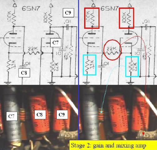
The second preamp tube/Stage 2; gain stage and mixing amp. Caps C7 - C9 show pretty clearly; t'were my amp, I'd replace them all. On the right, the red boxes are the plate resistors and the blue boxes the cathode resistors; I'd replace them all including the 22K resistor from the cathode of V2A to the cathode of V2B; that resistor couples the stages ... needs either a new carbon composition or metal film ... more on the subject below.
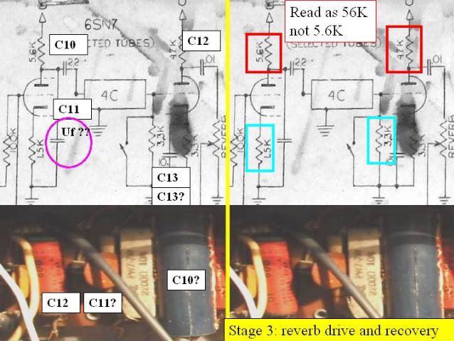
The third preamp tube/Stage 3; Reverb drive and recovery. Unfortunately, this and the phase inverter section of the schematic are pretty bushed up. For example; [C11] - the schematic doesn't identify it's value, [C10] - the draftsmanship is pretty murky there 22uf? 2.2uf? .22uf?, [C13] if it's really a 10uf cap, I don't see one in the pic and I question it's value anyway. More on the caps below: on the resistor side, same thing, replace the plate and cathode resistor but, unless you really have a 5.6K ohm in your amp, I'd read that as 56K.
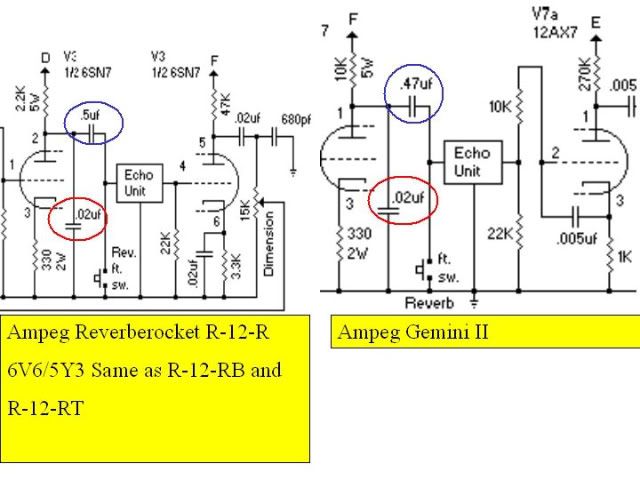
Reverb caps: in the image below; on the left is the reverb section from several early model Reverberockets and on the right, a later Gemini II; not getting into which came first the chicken (Ampeg RR) or the egg (Guild 98RT); we'll just leave it as they are strikingly similar including the use of 6__7 octal-based preamp tubes. Lecture: there are three ways to connect a reverb can and a tube; using an impedance-matching transformer (Gibson, Fender, Silvertone, others), using a capacitor (Ampeg, early Guild), and a speaker (later Guild). This design couples the tube section to the reverb can through a cap and its value really does matter.
You'll note that the cap in the blue circle is either .47 or .5 in the Ampeg design; not 22uf or 2.2uf. So, if the question is ... what goes there and since I really don't know what's in your amp and since there are striking resemblances between the RR and the 98RT and since there are way many more RRs still on the road than 98RTs, t'were my amp, if there's a .22uf on the circuit board, I'd put back a .22 at [C10]; if not, I'd put a .47 there and get on with it.
[C11]; I guess the phone rang while the guy was drafting ... but once again, Ampeg used a .02uf there - if you have one there, fine, if not, put a .02 there. Finally [C13] (not highlighted on the Ampeg image; the cathode bypass cap v. the 3.3K V3B cathode resistor (Amazing; both designs use a 3.3K cathode resistor :shock: :wink: ). Anyway, I don't know / can't tell what's in the amp but if it isn't a .02, I'd ignore the 98RT schematic and put a .02uf cap there. Finally and I'm not completely sure how important it is but if you can find [C11] and [C13] in polarized electrolytic .02/600v, use electrolytics; if you can't find them, you can use Mallory 150s @ 600V.
The fourth preamp tube/Stage 4; Phase Inverter/Driver. Cs 15, 17, and 18 are clearly .02/600v, replace with Mallory 150s or equal at 600V. I question the values of [C14] and [C16]. Electrolytics or non-polarized caps in those values would be too large to fit on the circuit board; there's a 500uf back in Stage 1 which I'm guessing is that battery-sized thing but wouldn't be surprised to find that it's substantially smaller. There is just about no chance that the draftsman intended picofarads (pf) as opposed to microfarads (uf) but stranger things have happened.
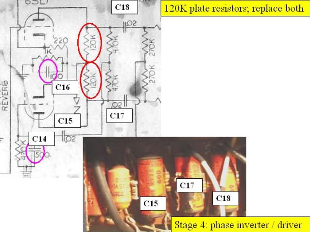
In both cases, [C14] and [C16] are bypassing cathode resistors for each's tube half and the expectation would be something in the 20-25uf range which, I think one of them is based on the pic but can't be sure. Anyway, a 100uf or 500uf cap would be so large that it wouldn't physically fit so .... Replace the 120K plate resistors, and ... in for a dime, in for a dollar, I'd recommend the 270K and 470K resistors too. Finally, the 220 ohm and 1K resistors on the cathode of V4A form a voltage divider that feeds V4B ... I'd replace those too; common values ... wtf ... you've got the board torn up anyway.
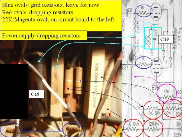
Power Supply Dropping Resistors; far right edge of the board viewed from the rear. Value as marked, common, and readily available. The resistor in the magenta circle is mounted further to the left on the circuit board. [C19] is the cathode resistor bypass cap for the 6V6s; it must be replaced and since accuracy counts, I'd replace the 250 ohm resistor too; 5 is better but not less than 2 watt rating. If you have the 1K grid resistors, replace them, otherwise unless they test as badly drifted, I'd replace them; if ok, they'll generate some nice grunge going into the output tubes.
Source; I used Antique Electronics A little more than some sources but the closest I can get to one-stop shopping ... quick shipping via USPS.
Carbon composition v. carbon or metal film; I used carbon comps for the most part; the values I want and they are not as quiet as carbon or metal films but that means they necessarily generate a little sonic trash which of course the original amp did in showroom condition. Your choice, either is ok.
Coupling caps; I prefer Mallory 150s ... others prefer Gouda cheese; the Mallorys are commonly available, inexpensive, and tonally neutral ... can use what you want but I'd avoid the knee-jerk towards Sprague Orange Drops; a little too crisp and antiseptic for my ears.
Make plenty of sketches and drawings; if you have to stop, you can always start back up where you left off; note other stuff; 'white wire to tube #1' .. it'll help you get oriented and once you draw what you have, mark off what you've replaced. As some of us geezers age, relying strictly on memory ... well ... that gets a little iffy too. :wink:
The second preamp tube/Stage 2; gain stage and mixing amp. Caps C7 - C9 show pretty clearly; t'were my amp, I'd replace them all. On the right, the red boxes are the plate resistors and the blue boxes the cathode resistors; I'd replace them all including the 22K resistor from the cathode of V2A to the cathode of V2B; that resistor couples the stages ... needs either a new carbon composition or metal film ... more on the subject below.
The third preamp tube/Stage 3; Reverb drive and recovery. Unfortunately, this and the phase inverter section of the schematic are pretty bushed up. For example; [C11] - the schematic doesn't identify it's value, [C10] - the draftsmanship is pretty murky there 22uf? 2.2uf? .22uf?, [C13] if it's really a 10uf cap, I don't see one in the pic and I question it's value anyway. More on the caps below: on the resistor side, same thing, replace the plate and cathode resistor but, unless you really have a 5.6K ohm in your amp, I'd read that as 56K.
Reverb caps: in the image below; on the left is the reverb section from several early model Reverberockets and on the right, a later Gemini II; not getting into which came first the chicken (Ampeg RR) or the egg (Guild 98RT); we'll just leave it as they are strikingly similar including the use of 6__7 octal-based preamp tubes. Lecture: there are three ways to connect a reverb can and a tube; using an impedance-matching transformer (Gibson, Fender, Silvertone, others), using a capacitor (Ampeg, early Guild), and a speaker (later Guild). This design couples the tube section to the reverb can through a cap and its value really does matter.
You'll note that the cap in the blue circle is either .47 or .5 in the Ampeg design; not 22uf or 2.2uf. So, if the question is ... what goes there and since I really don't know what's in your amp and since there are striking resemblances between the RR and the 98RT and since there are way many more RRs still on the road than 98RTs, t'were my amp, if there's a .22uf on the circuit board, I'd put back a .22 at [C10]; if not, I'd put a .47 there and get on with it.
[C11]; I guess the phone rang while the guy was drafting ... but once again, Ampeg used a .02uf there - if you have one there, fine, if not, put a .02 there. Finally [C13] (not highlighted on the Ampeg image; the cathode bypass cap v. the 3.3K V3B cathode resistor (Amazing; both designs use a 3.3K cathode resistor :shock: :wink: ). Anyway, I don't know / can't tell what's in the amp but if it isn't a .02, I'd ignore the 98RT schematic and put a .02uf cap there. Finally and I'm not completely sure how important it is but if you can find [C11] and [C13] in polarized electrolytic .02/600v, use electrolytics; if you can't find them, you can use Mallory 150s @ 600V.
The fourth preamp tube/Stage 4; Phase Inverter/Driver. Cs 15, 17, and 18 are clearly .02/600v, replace with Mallory 150s or equal at 600V. I question the values of [C14] and [C16]. Electrolytics or non-polarized caps in those values would be too large to fit on the circuit board; there's a 500uf back in Stage 1 which I'm guessing is that battery-sized thing but wouldn't be surprised to find that it's substantially smaller. There is just about no chance that the draftsman intended picofarads (pf) as opposed to microfarads (uf) but stranger things have happened.
In both cases, [C14] and [C16] are bypassing cathode resistors for each's tube half and the expectation would be something in the 20-25uf range which, I think one of them is based on the pic but can't be sure. Anyway, a 100uf or 500uf cap would be so large that it wouldn't physically fit so .... Replace the 120K plate resistors, and ... in for a dime, in for a dollar, I'd recommend the 270K and 470K resistors too. Finally, the 220 ohm and 1K resistors on the cathode of V4A form a voltage divider that feeds V4B ... I'd replace those too; common values ... wtf ... you've got the board torn up anyway.
Power Supply Dropping Resistors; far right edge of the board viewed from the rear. Value as marked, common, and readily available. The resistor in the magenta circle is mounted further to the left on the circuit board. [C19] is the cathode resistor bypass cap for the 6V6s; it must be replaced and since accuracy counts, I'd replace the 250 ohm resistor too; 5 is better but not less than 2 watt rating. If you have the 1K grid resistors, replace them, otherwise unless they test as badly drifted, I'd replace them; if ok, they'll generate some nice grunge going into the output tubes.
Source; I used Antique Electronics A little more than some sources but the closest I can get to one-stop shopping ... quick shipping via USPS.
Carbon composition v. carbon or metal film; I used carbon comps for the most part; the values I want and they are not as quiet as carbon or metal films but that means they necessarily generate a little sonic trash which of course the original amp did in showroom condition. Your choice, either is ok.
Coupling caps; I prefer Mallory 150s ... others prefer Gouda cheese; the Mallorys are commonly available, inexpensive, and tonally neutral ... can use what you want but I'd avoid the knee-jerk towards Sprague Orange Drops; a little too crisp and antiseptic for my ears.
Make plenty of sketches and drawings; if you have to stop, you can always start back up where you left off; note other stuff; 'white wire to tube #1' .. it'll help you get oriented and once you draw what you have, mark off what you've replaced. As some of us geezers age, relying strictly on memory ... well ... that gets a little iffy too. :wink:
boss55chevy
Junior Member
- Joined
- Mar 26, 2009
- Messages
- 15
- Reaction score
- 0
WOW! You've done a ton of work here Capn'! LTG is lucky to have you on board! Thank you again!
B
B
Hi Barry; aw pshaw ...boss55chevy said:WOW! You've done a ton of work here Capn'!
 :wink: The truth is I'm as interested in learning about this amp as you are. My hope and expectation is that when you're done, you'll be able to tell us all about the character and tone of Guild's take on the classic Ampeg Reverberocket. Based on its reputation, if your amp gets anywhere in the ballpark, I think you'll be pleased. Let me know if there's any way I can help. John