Hi Barry; I've been reviewing the 98RT schematic in anticipation of your rehab work; hope this helps. All the images
Here.
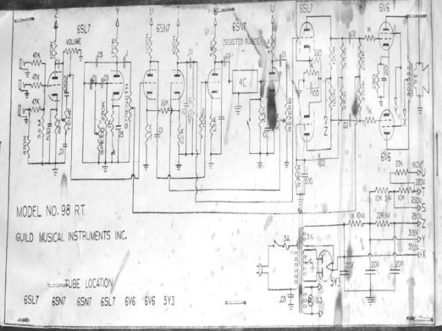
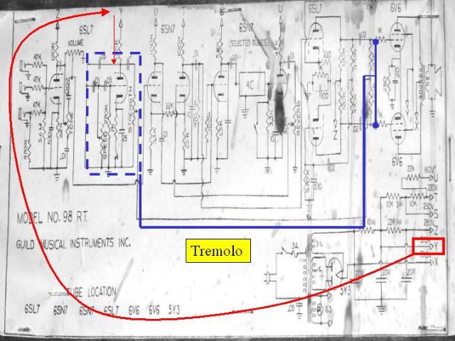
Reference Schematic:
Reverb:
The reverb signal is taken from V1A (left half) downstream of the tone and volume controls and is fed (magenta line) to the grid of V2A (left half). For the time being, ignore the dotted red line and follow the magenta line as it heads to the grid of V3A - the reverb driver - where it is amplified again and is coupled to the reverb can by a .22 capacitor; this is an Ampeg design feature. After it comes out of the reverb can, it sees a switch - red oval - connected to ground. When the reverb is switched off, the signal coming out of the reverb can is grounded out. The reverb signal - if on - is recovered by V3B - reverb recovery - and is re-amplified.
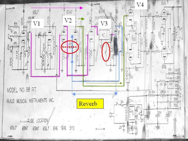
If the switch is in the 'on' position, then the 'verbed signal - the light blue line - is returned to the signal path at the grid of V2B where it is mixed with the dry signal. The signal, dry if the reverb is off or wet if on - the olive line - now boosted by V2B continues to the phase inverter / driver and appears at the grid of V4A and out via the 6V6s. The dotted red line - a 22K resistor - couples the two V2 sections together and assures that if the reverb is switched off, there will still be a dry signal which is fed to V2B at the cathode. As with the tremolo, all the passive components of this circuit are subject to load because everything ahead of the footswitch is always on.
Tremolo:
The power for V1B - the tremolo oscillator - is taken from power supply tap 'Y' and appears on the plate of V1B. The function of the tube half is to generate pulsing DC power as set by the speed and depth controls. The line signal never passes through V1B; it's output is applied to the 6V6 grid bias resistors. When the switch is on, the grid voltage of the 6V6 swings up and down causing the volume to go up and down according to the control settings and causes the oowaaoowaaoowaa ...
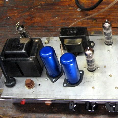
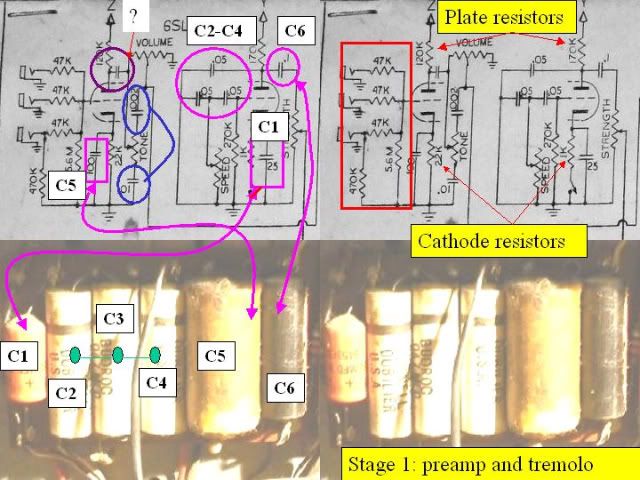
Stage 1:
Caps on the left: V1 is divided between preamp and controls functions and tremolo. Each 1/2 has its own cathode bypass capacitor the contributes to the tube half's bias, gain, and frequency response. For whatever reasons, V1A has a 100uf bypass cap [C5] and V1B has a 25uf cap [C1] a common value. Both need to be replaced. The tremolo circuit has three .05 caps [C2-C5]. The failure of one or more of these caps that are always on is the primary cause of no/low tremolo. If it were my amp, I'd replace them whether they worked or not. C6 is a coupling cap; my inclination is to replace but it's your choice. The tone caps are shown in the blue circle. They are normally mounted on or between the volume and tone controls and not on the circuit board. If they aren't defective, I'd leave them alone. Finally, there's a coupling cap identified by maroon circle and a
Question Mark. The missing value is a drafting error, likely to be anything from .01 to .05; whatever it is, it'll be the only one at that end of the board that hasn't been identified so far.
Resistors on the right: The grid stopper and leak resistors shown in the red box are likely mounted on the jacks; they don't do a lot of work and unless you have reason to think one or more is bad, I wouldn't mess with them. On the right, the cathode and plate resistors - identifiable by their color bands but covered up by the caps - they all need to be replaced. The 120K value can still be found, if you have trouble with the 170K, use 150K ... the values are not that critical anyway ... the cathode resistor values easy to find. Finally, that 270K resistor above and to the right of the Speed control on the schematic; he's a worker bee ... he gets replaced.
More as I get the other sections finished. John
")